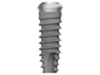
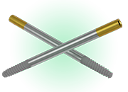
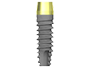
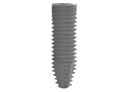
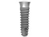
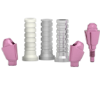
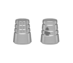
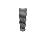
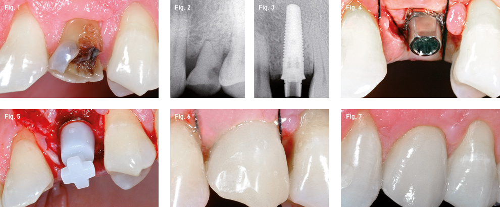
As part of a series of in-depth studies on prosthetic protocols, two clinical cases are presented that use the mounter from the Global implant line as a temporary abutment to make the immediate temporary crowns, with significant time and cost saving. The Global implant system is a screw fixture with conical body and double octagonal internal connection. The outstanding precision of the abutment and the special patented connection make it an excellent implant for single-tooth replacement. An important feature is that this implant is positioned in the surgical site with a mounter that, if left connected to the actual fixture, acts as a provisional abutment: it is sufficient to place it on top of a special dedicated cap in resin and take an impression with traditional materials for obtaining a temporary prosthesis to be cemented. The immediate temporary prosthesis was manufactured by following the characteristics of resistance, passivation and accuracy with reduced execution times (within 4 hours).
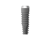
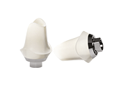
The double octagonal connection revealed to be extremely retentive and no disconnection between the implant and abutment was verified in 300 of the cases treated over a period of 36 months. The final crowns in metal-ceramic or in zirconium-ceramic were cemented with hardening auto/photo composite cement.